You definitely know that one particular smell you get when your electric appliance or wires have burned away due to a short circuit, right? This causes a state of panic and a warning of some serious expenses. The same can happen in the case of PCBs too. Just like wires burn out, PCBs can short circuit too. So, the next time you get that weird yet particular smell from your electronic device, you may guess that it is a short circuited PCB. But, don’t just jump to the decision. Make sure you know that it is that particular fault, and not something else. So, how do you make a check? There are four important steps you can follow to check for a short circuit in a PCB assembly from India. Here they are.
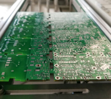
Step 1 – Visual inspection
The first and foremost step is that of visually inspecting your PCB. You can use a magnifying glass or a low magnification microscope. Look for tin whiskers between solder joints and pads, or any kinds of cracks or blobs of solder. Check for all the vias; poor plated vias can create a short circuit between layers. Burned spots on the PCB mean the short is really bad! If you cannot see any such problems visually, you will need to go down further into the internal layers of the PCB. So, how do you do that? Through Infrared Imaging. Using an infrared camera, you can locate areas where a large amount of heat is being generated on the PCB.
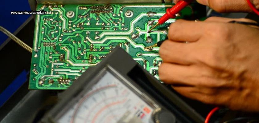
Step 2 – Multimeter testing
If your eyes are unable to do the job because the short may be a complicated or unnoticeable one, you will need to use a multimeter. This tool helps check the resistance between different points in the circuit. Track down the physical locations having problems using this tool. Short circuits may also involve a ground plane. Set one probe on a ground connection, and touch the other probe throughout other conductors on the board. The conductors that are not tied to ground will read a very high resistance. If the multimeter reading is low, but you do not have an inductor between the conductor and ground, you may be having bad components then. Using a multimeter, you must measure the resistance between pins on an IC or connector. Also, check that the resistance between pads/pins with respect to each other and the ground connection is low.
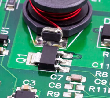
Step 3 – Component checking
If none of the above works to help you, it may be faulty components, or incorrect installation of your components. Check any suspect components. You may also check for any bulges in the PCB indicating that a particular component has gone bad or burnt.
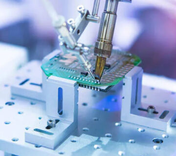
Step 4 – Destructive testing
With nothing in hand yet, the last retort is then destructive testing, which requires an X-ray imaging unit to examine the interior of the board without destroying it. However, if you don’t have access to an X-ray imaging unit, you can then remove your components and run your multimeter tests again. This will help to easily access every point of the PCB, minus the components. It will also help to test whether the board itself is defective, or if the pads on the board are faultily bridged internally.
All of the above is definitely very time-consuming and grueling. To avoid all such labourious tasks, you must make sure that you bring in only tested PCBs into your premises before installing them into your products. Thus, you need a manufacturer who builds the best PCBs and tests them rigorously before delivering them to you. Miracle Electronics is one such manufacturer who uses only the best components to build PCBs, and has every PCB assembly from India tested at the in-house test fixture before delivering the same to clients.