There is a rising urge of electronics usage in the market today, which has been driven by a steady stream of design innovation. Industrial and consumer markets expect new product iteration to provide enhanced performance and increased functionality, packed into a smaller size. To be able to satisfy all these capabilities, it is important that components are chosen very carefully so that they can provide optimal performance and value to end-users. It is important to understand how each component used can have an effect on the ultimate performance of the design.
What are high-frequency transformers?
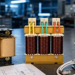
High-frequency transformers operate using the same principles as standard transformers, with the only main difference being that they operate at much higher frequencies. Where normal transformers operate at 50-60 Hz, high-frequency transformers operate between 20 KHz and 1 MHz. One main benefit of using high-frequency transformers is that they are smaller in size. The higher the frequency, the smaller the transformer size. And, because the size is smaller, the copper wire used is also less, thus reducing the losses, and helping the transformer become more efficient.
The challenges
However, the small size, lesser weight, and higher power desnity also poses a number of challenges. One such issue is minimizing skin and proximity effects.
Skin effects are caused by the tendency of high frequency currents to flow on the surface of the conductors. The losses due to skin effect can be reduced through the use of Litz wires, which are constructed by weaving multiple smaller conductors together to make an equivalent larger wire gauge. The size of each individual strand is determined by the intended operating frequency, with smaller strands being used for higher frequencies. The weaving process enables each strand to occupy a space near the skin of the Litz wire at some point in the length of the wire, allowing the current to flow more evenly through all the strands.
Proximity effects are caused by magnetic fields from adjacent conductors, either in adjacent windings or in adjacent layers, which causes the current to flow in unintended patterns or in eddy currents. This creates excessive resistance within the wire, and unintentional power loss. To minimize proximity effects, selecting a core that allows an increased number of turns or layers can help; or you can use foil winding layers, rather than round wires. To minimize the losses caused by core gaps, multiple gaps on the core leg can be used in a way that each gap is smaller; or you can use a physical barrier like tape to keep the winding away from the gap.
The topologies
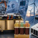
The efficiency delivered by an SMPS transformer is critical for modern electronics, and has facilitated the development of a large number of topologies to meet many design requirements. Some of these include buck, boost, buck-boost flyback, forward, and push-pull. High frequency SMPS transformers are high-efficiency and high-robust power-mode transformers, which are used mainly in electronic and communication devices, predominantly in power management chip LDO power supplies, 1.8v logic circuits, RF circuits, and external loads. High frequency SMPS transformers are used in high-frequency inverters and high-frequency inverter welding machine. The main function of such high-frequency transformers is the transfer of energy or storage of energy, depending upon the operating mode of the switching power supply.
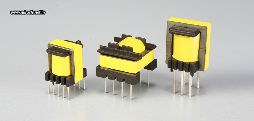
Miracle Electronics specializes in manufacturing and designing various high-frequency transformers, one of them being the SMPS transformer, each being of high quality, making us the most respected SMPS transformer manufacturer in India.