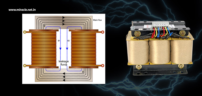
Three-phase transformers serve as the foundation for dependable and continuous electricity supply in a variety of industries and applications. Whether you are operating motors, supplying switchgear, or incorporating renewable energy sources, the transformer’s capacity to function safely and efficiently hinges on numerous engineering factors – one of the most vital yet often neglected being impedance matching. Improper impedance matching can lead to overheating, load imbalance, voltage fluctuations, and even equipment failure. While impedance may seem like a minor specification detail, it directly impacts transformer safety, efficiency, and longevity. This article explores why impedance matching matters, the risks of mismatched systems, and how engineers and buyers can ensure proper specifications for stable, high-performance transformer operations.
What is transformer impedance?
Transformer impedance is a measure of the combined resistance and reactance within a transformer, expressed as a percentage of its rated voltage. It reflects the internal voltage drop under full load and serves to limit the short-circuit current during faults. In three-phase transformers, impedance plays a vital role in ensuring proper voltage regulation, controlling fault levels, and balancing load currents—especially when transformers operate in parallel. A mismatch in impedance between parallel units can lead to uneven load sharing and operational instability. Typically, power transformer impedance ranges from 4% to 10%, depending on factors such as transformer size, winding design, core geometry, and application. Accurate impedance specification is essential for safe and efficient transformer operation in industrial power systems.
The importance of impedance in parallel transformer functionality
When several transformers are used in parallel, their impedance characteristics must be compatible. If the transformers do not have equivalent impedance values, the one with the lower impedance will draw more load current than the others. This discrepancy poses several issues.
- Overloading and overheating: A transformer that takes on more load than it is designed to handle will overheat, resulting in insulation deterioration and a shortened lifespan. In severe cases, this can lead to thermal shutdowns or irreversible damage.
- Voltage imbalance: Inconsistent impedance impacts the voltage regulation of each transformer, leading to voltage discrepancies between phases, which can harm connected devices or induce operational instability in motors and drives.
- Inefficient load distribution: The primary goal of operating transformers in parallel – load distribution – is compromised. The imbalance results in energy wastage, heightened losses, and variable power quality.
- Protection coordination challenges: Protection relays and circuit breakers depend on predictable current pathways. Mismatched impedance can create unforeseen fault current routes, making fault detection more complex and delaying the operation of breakers.
Impedance mismatch in parallel transformer setups can lead to serious operational issues, including overheating, poor voltage regulation, and unreliable fault protection. Ensuring impedance compatibility is critical for safe, balanced, and efficient power distribution, making it a non-negotiable consideration in every parallel transformer installation.
Key factors influencing transformer impedance
Transformer impedance is shaped by a range of design and material choices. Understanding these factors is essential for ensuring consistent performance, especially in systems requiring parallel operation. Here are the most critical elements that influence a transformer’s impedance characteristics.
- Transformer size: Larger transformers are designed to handle higher fault currents, which typically results in lower impedance levels—making size a critical factor in impedance performance and load-sharing compatibility.
- Winding configuration and geometry: Variations in winding turns, conductor thickness, layering technique, and physical layout directly affect both the resistive and reactive components of impedance, influencing how current is distributed under load.
- Core material and magnetic path: The type of magnetic core material and the length or cross-sectional area of the magnetic path impact the inductive reactance, thereby playing a crucial role in defining overall impedance.
- Manufacturing tolerances: Even when transformers share identical ratings, differences in manufacturer-specific tolerances can lead to slight impedance mismatches unless uniform specifications are clearly defined during the design and ordering phase.
A transformer’s impedance is not arbitrary; it’s the result of several deliberate design and material choices. Understanding these influencing factors enables better specification, seamless parallel operation, and long-term reliability in industrial power systems, helping engineers make smarter decisions during selection and procurement.
How to achieve impedance matching
Proper impedance matching is essential when operating transformers in parallel to prevent overloads and ensure efficient load sharing. Achieving this requires careful specification, installation practices, and post-deployment testing. Below are key steps engineers and procurement teams should follow to ensure reliable performance.
- Specify impedance tolerances in procurement: When ordering transformers for parallel operation, always indicate the impedance percentage and tolerance range. Ideally, the impedance difference should be within ±7.5% of each other, but a tighter range is preferable.
- Match kVA ratings and voltage classes: Avoid paralleling transformers with different ratings unless the application has been specifically designed to manage the imbalance. Even in such cases, matching impedance is essential for proportional load sharing.
- Use the same vector group: The vector group determines phase displacement and winding configuration. Mismatched vector groups render paralleling impossible, irrespective of impedance.
- Conduct load sharing tests: Post-installation, evaluate how transformers distribute load under varying conditions. Utilize clamp meters and thermal imaging to observe performance over time.
Achieving impedance matching is more than a technical requirement; it’s essential for preventing transformer stress, ensuring load balance, and maintaining power quality. With proper procurement specifications, matching ratings, and post-installation validation, engineers can secure a safe, stable, and high-performing transformer network.
Design strategies for impedance control
Transformer manufacturers employ various design techniques to fine-tune impedance levels and ensure compatibility across systems. These strategies help maintain balance and efficiency, particularly in complex or large-scale power setups. The following methods are commonly used to control and match impedance effectively.
- Modifying winding reactance: Adjusting the geometry, spacing, and interleaving of windings helps fine-tune the transformer’s reactance and overall impedance.
- Core design control: Altering the dimensions and cross-sectional area of the magnetic core influences the reactance component, aiding in impedance regulation.
- Incorporation of taps and buck-boost windings: Auto-transformer sections or tap changers assist in regulating output voltage and indirectly support impedance matching.
- Standardization across transformer fleets: For large-scale facilities or utilities, using a fleet of uniform transformers minimizes mismatches, streamlines inventory, and simplifies maintenance.
Thoughtful transformer design enables precise impedance control, reducing the risk of mismatches in parallel applications. Manufacturers must balance core and winding adjustments with standardization strategies to deliver dependable transformers capable of meeting the growing complexity of modern industrial and utility-scale power systems.
Don’t let impedance be an afterthought
Impedance matching is more than just a formality on a specification sheet; it is a vital design factor that influences whether transformers can safely and efficiently share loads in parallel. Neglecting this aspect can result in overheating, voltage fluctuations, inefficient energy consumption, and expensive system failures. It is thus essential to confirm a few things before procurement or parallel installation. These include affirmance that impedance values are aligned within acceptable limits, load sharing calculations have been performed, protection settings are properly coordinated, and that the transformer design adheres to applicable standards. A well-matched system not only operates cooler and lasts longer, but also provides the continuous, high-quality power that contemporary industries require.
Miracle Electronics – Your trusted three phase transformer manufacturer
When it comes to ensuring reliable impedance matching and high-performance transformer systems, Miracle Electronics stands out as the leading three phase transformer manufacturer in India. With decades of expertise in precision engineering and custom-built solutions, Miracle Electronics delivers transformers designed for optimal load sharing, minimal losses, and robust compliance with global standards. Whether your application demands parallel operation, sector-specific configurations, or stringent efficiency goals, Miracle Electronics ensures every transformer is manufactured with uncompromising quality, making it a trusted partner in power distribution across industries.